Minutemen Racing Leadership
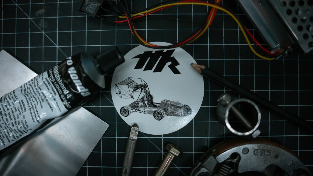
Manage the largest and most competitive on-campus design team at UMass Amherst. Bringing the team to its first-ever competition in August, and led the completion of the team’s first-ever car. Organize members using large Excel project-tracking spreadsheets, run admissions annually, and communicate with leaders of the Mechanical Industrial Engineering Department at UMass. Deliver weekly presentations to 50 members containing administration updates, event scheduling, weekly deliverables, and member expectations. Safely organize testing days by communicating with the UMass Land-Use Office and Amherst Fire Department using detailed testing procedure documents. Attend multiple weekly meetings, connect and engage with sponsors, and manage all business and engineering operations. Educate and develop talent by teaching design for manufacturing principles, holding SolidWorks and Ansys help sessions, and running formal design reviews.
MIE 313 Wrench Design Project
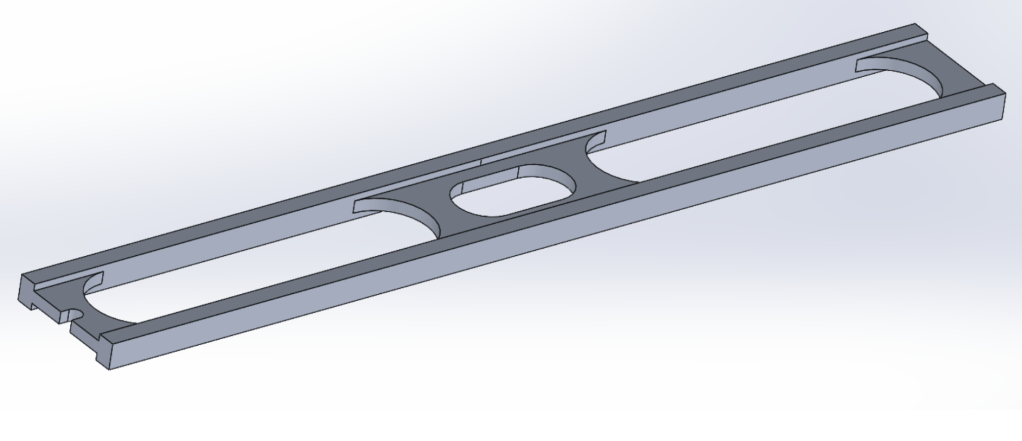
Design of Mechanical Component final project. Constraints included a required torque of 290 lb-in applied to a 5/16″ hex bolt, a weight limit of 32.6 grams, a required handle length of 4″, a required distance between the center of the bolt and the end of the wrench of 5″, and some additional functionality embedded. The assignment was to design a specific wrench to be used by an ultralight bikepacker. Design is impractical for daily use, but passes all constraints. A two-handed design splits the required torque in half, an I-Beam profile provides a strong second moment of inertia, and large cutouts significantly reduce weight. Designed with manufacturability in mind, this wrench was able to be manually machined in less than 20 minutes. The entire length of the provided stock was utilized to retain maximum torque application. The I-Beam profile and large cutouts were made with a 3/4″ end mill, before switching to a 1/2″ end mill for the center bolt slot. Finally, a tire spoke wrench was added as an additional feature.
MIE 375 PCB Mounting Project
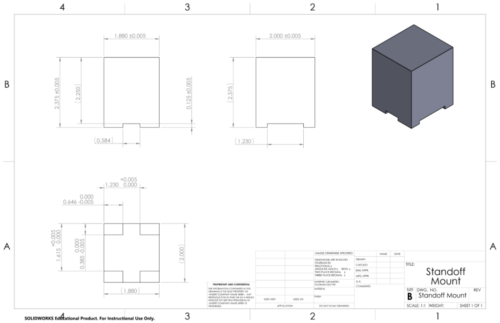
Manufacturing Processes project as a member of the manual machining subgroup. The project required collaboration between several groups of engineers, each working on an independent component to meet overarching assembly requirements. The manual machining subgroup was tasked with designing and manufacturing a standoff mount that interfaces with a 3D printed component and satisfies the final height requirement of a PCB, which gets secured on the top of this component. Design prioritized ease of manufacturing, utilizing multiple passes with a single 1/2″ end mill to create five final parts, each within the required tolerances. These parts were then passed on to a CNC machining subgroup, which completed the final cuts on each component.
FSAE Radiator Mounting Leadership
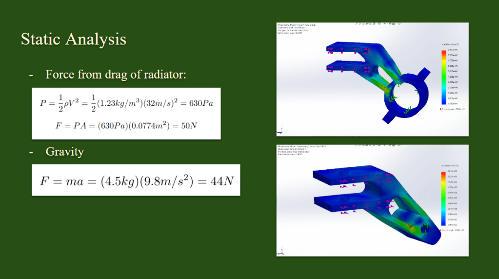
Assigned and assisted two freshmen Mechanical Engineers on the development of their first assembly to be attached to the FSAE car, a system of components that secures the radiator to the chassis. Taught SolidWorks, FEA, CFD, design for manufacturing, and design for assembly principles. Guided subteam members on preparing for formal design reviews and set development deadlines. After completion of this project, members were able to consistently design components in SolidWorks, utilize FEA to validate material choice and component geometry, and understand design for manufacturing principles. Final assembly includes three 3D printed components, two that attach the radiator directly to the chassis, and one that attaches the radiator to a tie rod. Also instructed team members on the cutting and tapping of the tie rod used in the assembly. This design process helped to develop valuable engineering skills for Minutemen Racing team members.
FSAE Rear Wing Manufacturing
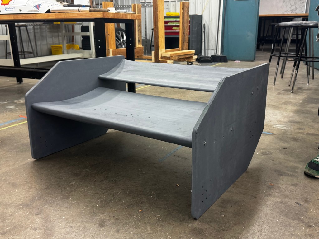
Participated in the manufacturing of a rear wing for an FSAE car, utilizing foam cutting and fiberglass molding. Manufactured a total of two endplates and two different airfoils, each originally cut out of foam and layered with fiberglass, including holes for fasteners and future mounting points. First, each component was cut to size out of foam, using laser-cut templates for each airfoil. Once each foam component was cut to size, fiberglass sheets were cut to size and layered over the foam. After using epoxy to set each fiberglass sheet in place, defects were sanded off, utilizing a fume hood and proper PPE. Finally, the wing was able to be assembled, with fasteners securing to inserts that were set into the foam.
FSAE Rear Wing Mounting
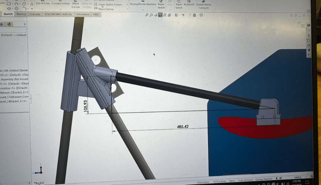
Designed and manufactured a rear wing mounting system for an FASE car, utilizing SolidWorks for CAD modeling, Ansys for FEA testing, and 3D printing principles for manufacturing. A final design report was made using LaTeX in Overleaf and brought for review by the E-Board. Three components are attached to the upper roll hoop on each side of the chassis, connected with epoxy to a carbon fiber tube, and then connected with epoxy again to the mounting points on the largest airfoil of the wing. Mimicking a swan-neck mounting design, this minimizes both weight and manufacturing costs. Final assembly included nylon printed components and additional mounting points on each endplate.
